Livestock judging involves evaluating animals based on their anatomical structure, breed standards, and market suitability․ It is a skill that enhances critical thinking and decision-making abilities, essential for agricultural professionals and enthusiasts alike․
1․1 Overview of Livestock Judging
Livestock judging is the process of evaluating animals to determine their quality, productivity, and suitability for specific purposes, such as breeding or market production․ It involves comparing animals within a class to identify their strengths and weaknesses; Judges assess factors like anatomy, conformation, and breed characteristics to rank animals․ This practice is essential in agriculture, helping producers select superior animals for their operations․ Livestock judging also fosters critical thinking, observation, and decision-making skills, making it a valuable educational tool․ Whether for competitions or practical farming, livestock judging provides a structured approach to understanding animal value and improving agricultural outcomes․
1․2 Importance of Livestock Judging
Livestock judging is fundamental for evaluating animal quality and productivity, ensuring the selection of superior individuals for breeding or market production․ It plays a critical role in competitions and practical farming, helping producers enhance their herds and improve agricultural outcomes․ By fostering critical thinking, observation, and decision-making skills, livestock judging empowers participants to make informed choices․ It also promotes agricultural education, equipping youth with essential skills for future careers․ Additionally, livestock judging supports the preservation of breed standards and genetic diversity, safeguarding the integrity of livestock production․ Its impact extends beyond individual farms, contributing to the overall advancement of the agricultural industry and food security․

Basics of Livestock Judging
Livestock judging involves evaluating animals based on their quality, structure, and productivity․ It requires observation, comparison, and decision-making skills to assess cattle, sheep, and swine effectively․

2․1 Understanding the Purpose of Livestock Judging
Livestock judging serves to evaluate animals for productivity, quality, and adherence to breed standards․ It helps producers select superior genetics, enhancing herds and meeting market demands; Judges assess structure, health, and potential performance, ensuring informed decisions for breeding and production․ This process promotes transparency and consistency in the livestock industry, fostering fair competition and continuous improvement of animal quality․ By understanding the purpose, participants gain insights into animal husbandry and market needs, contributing to sustainable and efficient farming practices․
2․2 Key Principles of Livestock Evaluation
Livestock evaluation relies on assessing conformation, muscling, movement, and overall breed characteristics․ Judges must prioritize structural soundness, as it directly impacts an animal’s productivity and longevity․ Breed standards guide evaluations, ensuring animals align with expected traits for their purpose, whether for meat, dairy, or breeding․ Muscling and body composition are critical for determining market value, while movement reveals joint health and mobility․ Consistency and fairness are essential, with judges applying uniform criteria to all animals․ Understanding these principles enables effective and accurate livestock evaluation, ensuring decisions align with industry standards and market demands․
2․3 Essential Skills for Effective Judging
Effective livestock judging requires a combination of critical thinking, keen observation, and in-depth knowledge of animal anatomy and breed standards․ Judges must possess strong analytical skills to evaluate and compare animals accurately․ Attention to detail is crucial, as subtle differences in conformation, muscling, and movement can significantly impact an animal’s value․ Decision-making skills are equally important, as judges must quickly and confidently rank animals based on their assessments․ Additionally, effective communication is key, as judges often need to articulate their reasoning clearly, especially in competitive settings․ By mastering these skills, judges can ensure fair, consistent, and informed evaluations, making them valuable assets in agricultural and livestock industries․

Animal Anatomy and Conformation

Understanding animal anatomy and conformation is fundamental in livestock judging․ It involves assessing external and internal structures to evaluate an animal’s productivity and longevity․
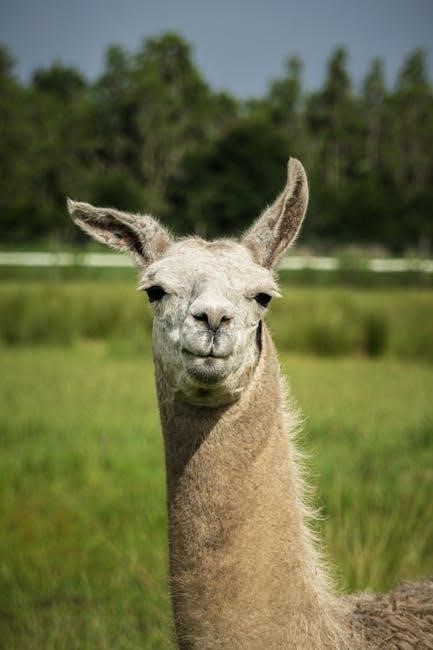
3․1 Identifying External Anatomy
In livestock judging, identifying external anatomy involves examining visible features to assess an animal’s quality and functionality․ Key areas include the head, ears, eyes, nose, neck, shoulders, back, ribs, loin, and legs․ Evaluating these parts helps determine the animal’s productivity and longevity․ Proper conformation ensures efficient movement and optimal performance in their intended roles, such as meat production or breeding․ Judges must recognize deviations from ideal structures, as these can impact the animal’s utility and overall value․

3․2 Understanding Internal Anatomy
Understanding internal anatomy is crucial for evaluating an animal’s health, productivity, and longevity․ Key internal systems include the digestive, respiratory, and muscular systems․ The digestive system’s efficiency impacts nutrient absorption, while the respiratory system ensures proper oxygen intake․ The muscular system’s development influences meat quality and movement․ Evaluating internal anatomy helps assess an animal’s potential for growth, reproduction, and overall productivity․ While external traits are visible, internal structures often determine long-term performance and health․ Judges must consider how internal systems support the animal’s intended purpose, whether for meat production or breeding․ This knowledge aids in making informed decisions about an animal’s value and suitability․ Internal anatomy insights are vital for accurate livestock evaluation and decision-making․
3․3 Importance of Conformation in Judging
Conformation refers to the overall structure and alignment of an animal’s body parts․ Proper conformation is essential for functionality, longevity, and performance․ Judges evaluate how well an animal’s physical traits align with its intended purpose, such as meat production or breeding․ Correct alignment of legs, joints, and body proportions ensures efficient movement and reduces the risk of lameness or injury․ Good conformation also enhances productivity, as it allows animals to perform optimally in their respective roles․ Assessing conformation helps identify animals that are structurally sound and capable of meeting market demands․ This aspect of judging ensures that selected animals are not only productive but also durable, making conformation a cornerstone of livestock evaluation and decision-making․
Breed Characteristics and Standards
Breed characteristics and standards define the physical and genetic traits of livestock breeds, guiding their evaluation for specific purposes like meat production or breeding, ensuring quality and suitability․
4․1 Overview of Major Livestock Breeds
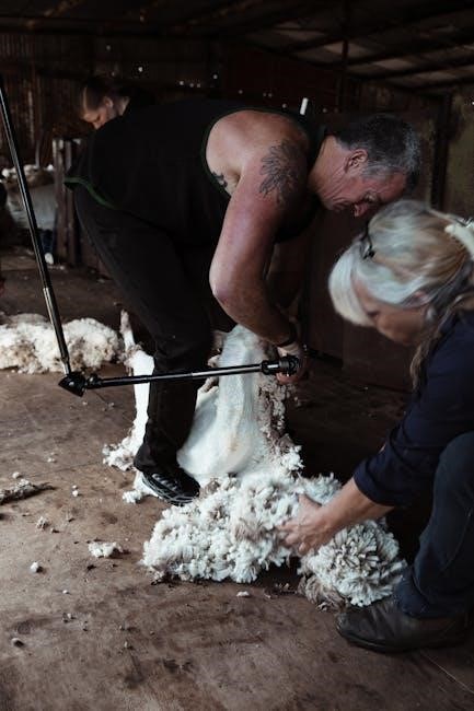
Livestock breeds are categorized based on their species and purpose, with cattle, sheep, goats, and swine being the most common․ Beef cattle breeds, such as Angus and Hereford, emphasize muscling and marbling for high-quality meat production․ Dairy breeds like Holstein prioritize milk yield․ Sheep breeds, including Merino and Rambouillet, are valued for wool and meat․ Pig breeds, such as Hampshire and Duroc, focus on growth rate and lean meat․ Each breed has unique traits, and understanding these differences is crucial for effective judging․ Breed characteristics often dictate their suitability for specific markets, making breed identification a key skill in livestock evaluation․
4․2 Breed Standards and Their Significance
Breed standards serve as guidelines that define the ideal characteristics of a specific livestock breed, ensuring consistency in selection and breeding․ These standards, often established by breed associations, outline key traits such as conformation, muscling, and reproductive efficiency․ Adherence to breed standards helps maintain the integrity and uniqueness of each breed, preserving genetic diversity․ In livestock judging, understanding these standards is crucial for evaluating animals accurately․ Judges assess how closely an animal aligns with its breed’s expectations, considering factors like structural soundness and productivity․ Breed standards also influence market value, as they often reflect the demands of producers and consumers․ Thus, they play a vital role in guiding selection decisions and improving livestock quality․
4․3 Role of Genetics in Breed Characteristics
Genetics play a pivotal role in shaping the distinct characteristics of livestock breeds, influencing traits such as conformation, muscling, and reproductive efficiency․ The genetic makeup of an animal determines its growth rate, feed efficiency, and susceptibility to diseases․ Breeders use selective breeding to enhance desirable traits, ensuring consistency within a breed․ For example, certain cattle breeds are genetically predisposed to superior marbling for beef quality, while others excel in milk production․ Understanding genetics helps judges evaluate how well an animal aligns with its breed’s intended purpose․ Genetic diversity is also crucial to maintain resilience and adaptability in breeds, preventing inbreeding issues․ This genetic foundation ensures that breeds remain viable for their intended agricultural roles, making it a cornerstone of livestock judging and breeding practices․
The Judging Process
The judging process involves systematically evaluating livestock based on predefined criteria, such as conformation, breed standards, and market suitability․ Judges assess each animal’s strengths and weaknesses, comparing them to industry ideals․ This process requires keen observation, knowledge of breed characteristics, and the ability to make sound decisions under competition settings․ Effective judges must remain impartial, ensuring fairness and accuracy in their evaluations․ The process culminates in ranking animals and providing clear, concise reasoning for their decisions, fostering transparency and educational opportunities for participants․

5․1 Preparing for a Judging Contest
Preparing for a livestock judging contest involves thorough study of animal anatomy, breed standards, and market priorities․ Judges must understand the structural and functional traits of livestock, such as muscling, skeletal alignment, and reproductive potential․ Familiarity with breed characteristics is crucial, as each breed has unique features that define its purpose․ Contestants should practice evaluating animals, comparing them to industry ideals, and organizing their thoughts logically․ Time management and organization are key, as contests often involve multiple classes and species․ Attending workshops, reviewing judging guides, and participating in practice sessions can enhance readiness․ A well-prepared judge demonstrates a clear understanding of livestock evaluation principles and the ability to articulate decisions confidently․
5․2 Evaluating Animals During the Contest
Evaluating animals during a judging contest requires a systematic approach to assess their quality and rank them accurately․ Judges compare each animal to industry standards and breed expectations, focusing on traits like muscling, skeletal alignment, and movement․ Attention to detail is critical, as subtle differences can determine placement․ Contestants must remain objective, avoiding personal biases, and base decisions on factual observations․ Animals are typically evaluated in groups, with judges comparing one to another to identify strengths and weaknesses․ Time management is essential, as contests often involve multiple classes and species․ Judges must also stay focused and maintain mental clarity to ensure consistent and fair evaluations throughout the event․
5․3 Delivering Oral Reasons
Delivering oral reasons is a critical component of livestock judging contests, requiring contestants to clearly articulate their decisions and rationale․ Judges must explain their animal placements, highlighting strengths and weaknesses, and justify their rankings․ Effective communication involves being concise, organized, and confident․ Contestants should focus on key traits such as conformation, muscling, and movement, comparing each animal to industry standards and breed expectations․ Proper diction, tone, and eye contact are essential for conveying credibility․ Oral reasons also demonstrate a contestant’s understanding of livestock evaluation principles and their ability to think critically․ This skill not only enhances judging accuracy but also fosters effective communication, a valuable asset in agricultural and professional settings․ Mastery of oral reasons distinguishes skilled judges and competitors․
Advanced Topics in Livestock Judging
Advanced techniques include comparative judging, leveraging technology for precise evaluations, and understanding the benefits of participating in contests to refine skills and industry knowledge effectively․
6․1 Comparative Judging Techniques
Comparative judging techniques involve evaluating multiple animals side-by-side to identify strengths and weaknesses․ This method enhances accuracy by allowing direct comparisons of conformation, breed characteristics, and market suitability․ Judges must consider each animal’s structure, movement, and adherence to breed standards․ By focusing on relative merits, participants develop a deeper understanding of ideal traits and flaws․ Effective use of comparative techniques requires practice and a strong foundation in livestock anatomy and breed standards․ These skills are honed through experience and training, enabling judges to make informed, consistent decisions in competitive settings․
6․2 The Role of Technology in Modern Judging
Technology has revolutionized livestock judging by introducing digital tools and software that enhance evaluation processes․ Judges now utilize apps and platforms to record scores, analyze data, and compare animals more efficiently․ AI-powered systems can assess anatomical features and predict market performance, aiding in objective decisions․ Virtual judging platforms enable participants to evaluate animals remotely, expanding accessibility for global competitions․ Technology also facilitates real-time feedback and educational resources, helping judges refine their skills․ These advancements ensure greater accuracy, consistency, and transparency in modern livestock judging, making it a cornerstone of the industry’s progression and adoption of innovative practices․
6․3 Benefits of Participating in Judging Contests
Participating in livestock judging contests offers numerous benefits, including enhanced critical thinking and decision-making skills․ It fosters teamwork, communication, and problem-solving abilities, as participants often work in groups and present oral reasons․ Judging contests also provide exposure to industry standards, allowing individuals to gain insights into market trends and breed characteristics․ Additionally, these events promote networking opportunities with professionals and like-minded individuals․ They encourage personal growth by building confidence and resilience, as participants learn to articulate their opinions clearly․ Moreover, judging contests provide practical experience, enabling participants to apply their knowledge of animal evaluation in real-world scenarios․ Overall, such contests are invaluable for developing skills and understanding the livestock industry․